Welcome to the documentation for the 2020 Autonomous Underwater Vehicle (AUV) known as "Kirby" or "Charybdis", developed by the Kennesaw State University AUV team. This documentation provides a comprehensive insight into the design, construction, and operation of Kirby, offering a detailed overview of its electrical, mechanical, and software components.
Main Structure
The electrical team focuses on creating an electrical system that had not only new features on the sub but also to make or redesign parts of the system to help with their performance and quality of life. Different software programs like Eagle CAD, LTspice, and Altium help develop and test out the designs of new circuits for the electrical system. Along with that, members are taught how to design circuit boards and solder components to help grow the team and the community.
Power Board
The sub utilizes a power distribution board that is divided into multiple parts. The first section connects the kill switches to 5 lithium polymer batteries which then connect to the motors, onboard computer, and sensors. The second section is managed through the kill switches that were designed for sending power to the rest of the electrical sub systems.
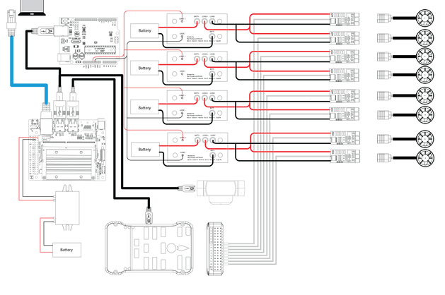 Figure 1: Power Board
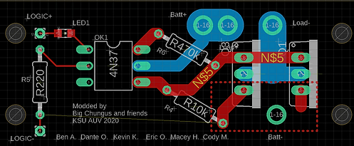 Figure 2: Kill Switch
Kill Switch
The use of kill switches is to manage the power distribution of the sub by acting as a way of killing all power to the sub via a switch on the back of the sub.
The current kill switches utilize recalculated track widths to prevent overheating and current overload. In addition, the current kill switches were designed for the physical geometry of the board to be directly attached to the chassis of the chamber along with bringing all the existing components closer together. This change eliminated excess height and width that was previously seen and allows for more electrical components to be on the frame of the sub.
Filter Circuit
This year, a lot of emphasis was directed toward frequency filtration and signal processing. The filter allows us to ignore irrelevant frequencies that do get detected by our hydrophone system. To complete this task, IC filters were chosen. There are three important modes on these ICs: low-pass, high-pass, and band-pass. For these tasks, our team worked with bandpass filters to focus on the projected frequencies at competition (25kHz, 35kHz, etc.) and filter out any frequency that is above or below the set frequency from the pinger in the pool. The plan was to use the LTC1068 chip since it is a clock tunable bandpass filter. This would allow the use of a microcontroller to send a PWM signal and vary the frequency to change the center frequency of the bandpass filter. This would enable the ability to switch what frequency is let through the filter on the fly.
Amplifier Circuit
It's very common that the incoming signal is too weak and needs amplification in order to be processed by the main system. Our team designed an amplifier circuit to amplify the frequencies trying to be detected through the IC filters. The filters are connected to a series of capacitors to help amplify the signals passing through the IC filters.
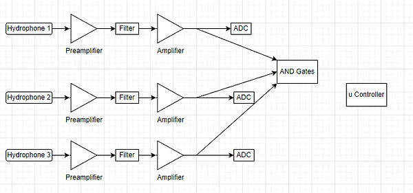 Figure 3: Filter and Amplifier Circuit
 Figure 4: Expanded Sub View
Main Structure
The mechanical structures on Charybdis consist of the hull, propulsion systems, and additional sub-systems (such as the torpedo launcher). The hull design can be divided into two main sub-components:
1.) Outer Frame: Provides overall structure and stability.
2.) Inner Frame: Comprising the structures that hold the housing tube, battery tubes, and computer components.
The hull is constructed from 6061-T6 aluminum plates. The plates were cut on a water jet and slotted together.
 Figure 5: Main Tube
 Figure 6: Battery Tubes
Inner Housing
All the subs' control electronics are housed in a large 8-inch acrylic tube to centrally house the sub’s critical controls. The sub also has four smaller acrylic tubes mounted to the end of the outer frame. Three of the tubes hold the subs 1000mAh batteries with a fourth tube for auxiliary system circuitry.
For propulsion, Charybdis is powered by eight T-200 Blue Robotic Thrusters. The thrusters are laid out in the Blue Robotics vector 6DOF configuration which gives the sub maximum maneuverability.
Torpedo System
One of the sub-systems we integrated with Charybdis is our torpedo launcher. The torpedoes are launched using a compressed CO2 canister. The launching mechanism uses a waterproof servo with a gearbox that translates the rotational motion to linear motion. A 3:1 ratio is used to amplify the linear force on the torpedo firing pin which triggers the canister release.
 Figure 7: Torpedo Flow Simulation
 Figure 8: Torpedo Launcher
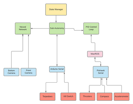 Figure 9: Software Architect
Software Architecture
The software architecture of Charybdis is built on a foundational structure utilizing the Robot Operating System (ROS), which provides a message-passing system, networking capabilities, and more. The packages we created were designed to take advantage of ROS and the open-source libraries that use it, including SMACH, MavROS, ROS Serial, OpenCV, and Tensorflow. Figure 9 shows the high-level overview of Charybdis and signals direction.
State Machine
High-level decisions about what Charybdis should do are made in a state machine implemented in SMACH, a ROS package that defines a state machine structure. Each state performs a specific task and is strung together to make more complex processes. Video input is received from two USB cameras, one forward-facing, and one downward-facing, and sent to the object detection algorithm via ROS. Once the network visualizes the detections, Charybdis can perform movements based on that information. The Neural Network takes two points from the field of view: one provided by the SSD (Single Shot Detector) architecture within TensorFlow and another provided by the center of the camera. The program calculates the error between the two points and processes the error through a PID control loop, then outputs an RC value published to MavROS. We use this information to calculate sub-movements and feed into our state machines.
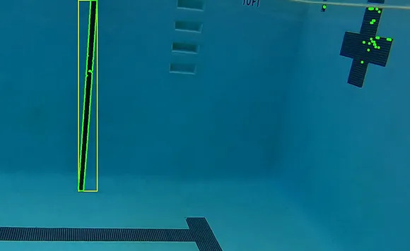 Figure 10: Single Shot Detection
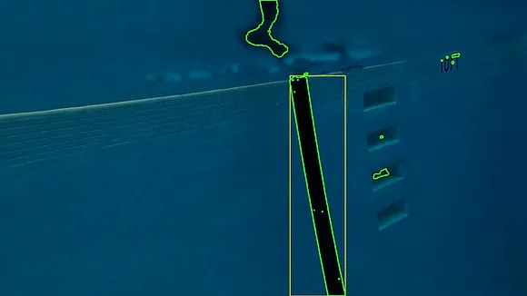 Figure 11: Single Shot Detection
Simulations
In addition to the issues we face with sub functionality, the COVID-19 caused increased difficulty with team communication and system testing. We decided that in order to mitigate these obstacles testing of Charybdis’ states and functions prior to an in-person test would be crucial. Thus, we decided to use Software-in-the-Loop with Ardusub, using MavROS to send communications. This allows us to get a visual 2D simulation running of Charybdis and to test functions and states before executing them on the physical sub in water. This has streamlined the software design process and improved the speed of implementation for new behaviors.